
-
×
 Digital Infrared Temperature Sensor Module MLX90614 in Pakistan
1 × 1,650.00 ₨
Digital Infrared Temperature Sensor Module MLX90614 in Pakistan
1 × 1,650.00 ₨


Most of us are more comfortable with 1, 2, 3, 4… rather than 001, 010, 011, 100. It mean to say that we will need a decimal code output in many cases rather than a raw binary output. We have many counter ICs available but most of them produce binary data as an output. We will again need to process that output by using decoders or any other circuitry to make it usable for our application in most cases. Let us now introduce you to a new IC named IC 4017.
It is a CMOS decade counter cum decoder circuit that can work out of the box for most of our low-range counting applications. It can count from zero to ten and its outputs are decode. This saves a lot of board space and time require to build our circuits when our application demands using a counter followed by a decoder IC. This IC also simplifies the design and makes debugging easy. This article discusses an overview of the IC 4017 datasheet.
What is an IC 4017 Decade Counter?
The CD4017 IC is a CMOS Decade counter and it is use in the applications of low-range counting. This IC will count from 0 to 10 and the circuit with an IC 4017 will save board space as well as the time necessary to design the circuit. It decade counter is similar to Johnson 10 stage decade counter. This CMOS IC is frequently used in designing the 10 LEDs-base circuits to run the light for beginners. So it is one of the most flexible counters because it counts up to 10 & also it includes 10 separate outputs. This IC includes the counter as well as the decoder.
Pin Configuration of IC 4017
A CMOS decade counter like 4017 IC includes a five-stage Johnson counter & 10 decoded outputs for counting up to 10 decimals. IC can be used in different counter circuits such as an LED chaser light & also a non-contact circuit with an AC detector. This IC includes 16-pins where 10 & 16 pins are output pins. This IC counts for every positive otherwise increasing edge input provided at the CLK input.
Here, the output begins from ‘0’ and moves to output ‘9. Once it reaches then the output will count at ‘9’ and again it repeats from 0 & continues this revolution similar to a ring counter. On each count among 0 to 9, the particular output pin can include a high state & the remaining output maintains low; simply one o/p will be high at a time.
For instance, if the count is presently three then the output at pin-7 is will be in a high state whereas the remaining pins are in a less state. If two cycles of the square wave are apply toward the clock input, then the output will shift to output 4 on the positive edge of the primary cycle which alters output-4 to high state & output-3 to low state.
Now the condition remains until another positive edge of the next cycle arrives, after that the o/p moves to pin1 or output 5 and maintains this condition. 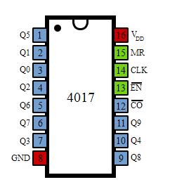
It has 16 pins and the functionality of each pin is explain as follows:
- Pin-1: It is the output 5. It goes high when the counter reads 5 counts.
- Pin-2: It is the output 1. It goes high when the counter reads 0 counts.
- Pin-3: It is the output 0. It goes high when the counter reads 0 counts.
- Pin-4: It is the output 2. It goes high when the counter reads 2 counts.
- Pin-5: It is the output 6. It goes high when the counter reads 6 counts.
- Pin-6: It is the output 7. It goes high when the counter reads 7 counts.
- Pin-7: It is the output 3. It goes high when the counter reads 3 counts.
- Pin-8: It is the Ground pin that should be connected to a LOW voltage (0V).
- Pin-9: It is the output 8. It goes high when the counter reads 8 counts.
- Pin-10: It is the output 4. It goes high when the counter reads 4 counts.
- Pin-11: It is the output 9. It goes high when the counter reads 9 counts.
- Pin-12: This is divided by 10 output which is use to cascade the IC with another counter to enable counting greater than the range support by a single IC 4017. By cascading with another 4017 IC, we can count up to 20 numbers. We can increase and increase the range of counting by cascading it with more and more IC 4017s. Each additional cascaded IC will increase the counting range by 10. However, it is not advisable to cascade more than 3 ICs as it may reduce the reliability of the count due to the occurrence of glitches. If you need a counting range of more than twenty or thirty, I advise you to go with the conventional procedure of using a binary counter followed by a corresponding decoder.
- Pin-13: This pin is the disable pin. In the normal mode of operation, this is connect to ground or logic LOW voltage. If this pin is connect to logic HIGH voltage, then the circuit will stop receiving pulses and so it will not advance the count irrespective of several pulses received from the clock.
- Pin-14: This pin is the clock input. This is the pin from where we need to give the input clock pulses to the IC to advance the count. The count advances on the rising edge of the clock.
- Pin-15: This is the reset pin that should be kept LOW for normal operation. If you need to reset the IC, then you can connect this pin to HIGH voltage.
- Pin-16: This is the power supply (Vcc) pin. This should be given a HIGH voltage of 3V to 15V for the IC to function.
This IC is very useful and also user-friendly. To use the IC, just connect it according to the specifications describe above in the pin configuration and give the pulses you need to count to the pin-14 of the IC. Then you can collect the outputs at the output pins. When the count is zero, Pin-3 is HIGH. When the count is 1, Pin-2 is HIGH, and so on as described above.


Reviews
There are no reviews yet.